


Welcome to Part II of a series of articles about the design and installation of water boreholes (water wells) for Agricultural Irrigation Systems. In Part II we start to look at the various activities that make up the design and construction of a water borehole.
In Part I we looked at why water wells are important to the supply of a reliable source of water for farm irrigation, the importance of determining the correct well location, the key component parts of a working water borehole, and finally we looked at some definitions that will be used in this article.
Water Well Design and Construction of Agricultural (Farming) Irrigation Systems
Preliminary Investigation
The National Ground Water Association (UK)
The preliminary investigation is the foundation upon which a well design depends. An examination of records from existing wells in the area should be made to determine yield, depth, and characteristics of the aquifers presently being used. Consultation should be made the National Ground Water Association which will be able to provide sufficient geologic data to help select the best well design with regards to water supply and construction cost.
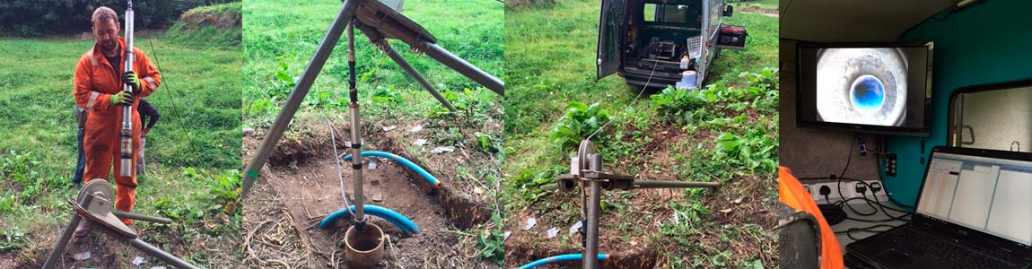
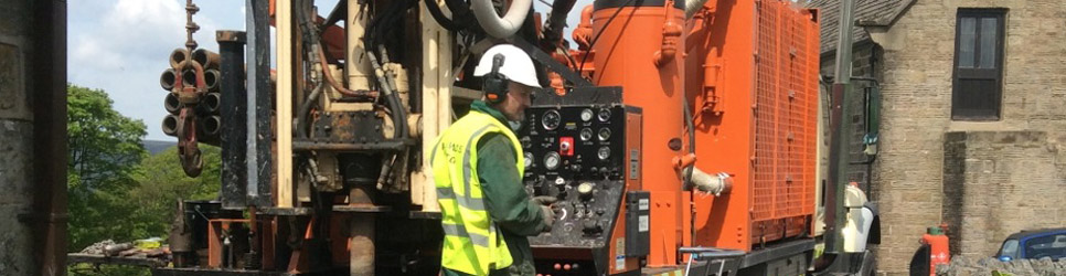
Water Borehole Test Drilling
If sufficient records are unavailable, test holes should be drilled to determine the water borehole drilling location with the best water production potential and to help formulate the production well design for the selected site. The information gained from test holes usually justifies the investment. In drilling test holes, samples of the aquifer should be collected so that permeability tests can be made. From the completed test holes, the well designer should determine:
- aquifer thickness
- aquifer depth
- static water level of the aquifer
- estimate the yield and specific capacity of a full-sized production well.
A water sample should be collected and analysed to determine the corrosion and/or incrustation characteristics of the water.
Waterseekers Well Drilling Services Ltd has over 50 years experience of commercial water well installations for agricultural and industrial usage. Please visit our main website and get in touch. We are always happy to advice you on your project.
Water Borehole Design Procedure
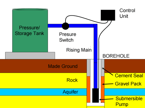
After the preliminary investigation and site selection, a well design can be selected which best utilizes the hydro-geological conditions present at the site. The cased portion of the well should be designed first, and then the intake portion of the well. The cased portion of the well consists of the well casing that serves as both a housing for the pump and as a vertical conduit through which water flows upward from the intake portion of the well to the level where it enters the pump (Figure 1). The casing (or well pipe) is a very critical element in well construction. Casing may be metallic (black iron or galvanized steel) or non-metallic (polyvinyl chloride (PVC) or ABS plastic). It must be adequately seated in a consolidated formation (limestone, sandstone, etc.) or attached to a screen suitably designed and situated in unconsolidated materials (shell, sand, gravel, etc.). The purpose of casing is to seal off materials that may enter the pumping system from strata other than the aquifer selected and prevent mixing between aquifers. To prevent contamination from surface flow into the well, the casing must be extended above surface flood water levels, and the top portion must be grouted with cement or an approved alternative material.
Casings are sealed in place with grout which protects against contamination by pollutants from the surface and acts as a seal for the casing seated into a consolidated formation. In areas where the beds of consolidated material that the casing is seated into are friable (crumble easily), the grout also helps to prevent deterioration of the casing seat (casing shoe) due to turbulence developed during pumping. Poor grouting may create problems later as pump impellers and other mechanical parts are scoured by small particles moving into the well around the casing shoe. Poor grouting may also create voids where eventual corrosion of the casing wall allows unconsolidated matter to enter the well.
Waterseekers Well Drilling Services Ltd has over 50 years experience of commercial water well installations for agricultural and industrial usage. Please visit our main website and get in touch. We are always happy to advice you on your project.
The well should be of sufficient diameter to allow the ascending water to move at a velocity of 5.0 feet per second or less up the well casing. Data from the preliminary investigation and chemical analyses of water samples should be reviewed to determine if the water is corrosive or encrusting. When necessary, extra heavy steel casing should be installed. In cases of severe corrosive water, stainless steel, PVC, or fiberglass casing should be used.
The capacity of individual wells is highly variable from location to location. Average estimates of expected capacities for various size wells are given in Table 1. Although Table 1 can serve as a general guideline, the specific capacity depends on the yield characteristics of the water-bearing formation and the design of the well. The overall installation must be carefully evaluated. For instance, although 1,000 gpm may be obtained from a 10-inch pump with reasonably good efficiency, the life cycle cost of a 12-inch pump installation may be less, even including the higher cost of the larger well.
The Water Well Screen
Commercially manufactured quality well screen should be used for the wells. The well screen should have an efficient design. A well screen is considered adequate when it allows ample sand-free water to flow into the well with minimum hydraulic head loss. A properly designed well screen should have close spacing of slot openings to provide uniform open area distribution, maximum open area per foot of length, V-shaped slot openings that widen inwardly, corrosion resistance, and ample strength to resist external forces to which the screen may be subjected during and after installation. Screens with tapered slots provide hydraulic efficiency and offer self-cleaning properties. Sand grains smaller than the screen opening are easily brought into the well in the development process, while large grains are retained outside.
Screen length is an important design consideration. A screen that is too short seriously affects the efficiency of the well, whereas a well screen that is too long causes problems such as cascading water, entrained air, and accelerated corrosion and/or incrustation. The optimum length of well screen is chosen with relation to the thickness of the aquifer, available drawdown, and stratification of the aquifer.
In an artesian aquifer, the lower 70% to 80% of the thickness of the water-bearing sand should be screened, assuming the pumping level is not expected to be below the top of the aquifer. It is generally not necessary to screen the entire thickness of artesian aquifers. About 90% of the maximum specific capacity can be obtained by screening only 75% of an artesian aquifer. An exception to this rule should be made when the aquifer is highly stratified and interbedded with low permeability layers. In this case, all of the aquifer may need to be screened.
Optimum design practice dictates that the maximum available drawdown in an artesian well should be the distance from the static water level to the top of the aquifer. If it is necessary to lower the pumping level below the top of the aquifer to obtain greater yield, the screen length should be shortened and the screen should be set at the bottom of the aquifer. Attempts should be made to design and construct the well so that the pumping level stays above the top of the uppermost well screen.
For water table wells, selection of screen length is something of a compromise between two factors. While high specific capacity is obtained by using as long a screen as possible, short screens provide more available drawdown. These two conflicting aims are satisfied, in part, by using an efficient well screen. Available drawdown in a water table well is the distance between the static water level and the top of the screen. Screening the bottom 1/3 to 2/3 of the aquifer normally provides the optimum design.
That’s it for probably enough for this week. Remember, you don’t have to know anything about the detailed installation of a water borehole, since we have it all covered, but it does make interesting reading to some.
Waterseekers Well Drilling Services Ltd has over 50 years experience of commercial water well installations for agricultural and industrial usage. You dont have to know about the above definitions becasue we undertake the Borehole Prognosis for you.
Commercial Water Borehole Turn Key Solutions
We offer a turn-key solution that covers not just the technical aspects such as borehole prognosis, but also every requirement typical of any large commercial water borehole project:
- Insurance
- Health and Safety
- Project Management
If you would like to talk to us about your project, we are happy to give no obligation advice. Visit our website, use the contact form, or call us on 01246 938499
In Part III, we will continue to expand on Water Well Design and Build.
Thanks for reading!
Jenny Hormell
Director
Waterseekers Well Drilling Services Ltd.
Post on 01 Dec 2014 by Water Well Drilling Enthusiast
Posted in
- borehole drilling
- Commercial
- Farming
- industrial water consumption
- irrigation
- Licensing
- poultry farming
- water borehole drilling
- water borehole installation
- water boreholes
- water footprint
- Water Supply
- water supply for farms
- water well drilling
- Water Wells and tagged agricultural water footprint
- water wells yorkshire