


Welcome to Part III of a series of articles about the design and installation of water boreholes (water wells) for Agricultural Irrigation Systems. In Part III we complete our look at the various activities that make up the design and construction of a water borehole. Please read Part II first.
Just to recap, in Part I we looked at why water wells are important to the supply of a reliable source of water for farm irrigation, the importance of determining the correct well location, the key component parts of a working water borehole, and finally we looked at some definitions that will be used in this article.
Water Well Design and Construction of Agricultural (Farming) Irrigation Systems
Water Borehole Design & Construction (Continued from Part II)
Well Screen
Commercially manufactured quality well screen should be used for the wells. The well screen should have an efficient design. A well screen is considered adequate when it allows ample sand-free water to flow into the well with minimum hydraulic head loss. A properly designed well screen should have close spacing of slot openings to provide uniform open area distribution, maximum open area per foot of length, V-shaped slot openings that widen inwardly, corrosion resistance, and ample strength to resist external forces to which the screen may be subjected during and after installation. Screens with tapered slots provide hydraulic efficiency and offer self-cleaning properties. Sand grains smaller than the screen opening are easily brought into the well in the development process, while large grains are retained outside.
Screen length is an important design consideration. A screen that is too short seriously affects the efficiency of the well, whereas a well screen that is too long causes problems such as cascading water, entrained air, and accelerated corrosion and/or incrustation. The optimum length of well screen is chosen with relation to the thickness of the aquifer, available drawdown, and stratification of the aquifer.
In an artesian aquifer, the lower 70% to 80% of the thickness of the water-bearing sand should be screened, assuming the pumping level is not expected to be below the top of the aquifer. It is generally not necessary to screen the entire thickness of artesian aquifers. About 90% of the maximum specific capacity can be obtained by screening only 75% of an artesian aquifer. An exception to this rule should be made when the aquifer is highly stratified and interbedded with low permeability layers. In this case, all of the aquifer may need to be screened.
Optimum design practice dictates that the maximum available drawdown in an artesian well should be the distance from the static water level to the top of the aquifer. If it is necessary to lower the pumping level below the top of the aquifer to obtain greater yield, the screen length should be shortened and the screen should be set at the bottom of the aquifer. Attempts should be made to design and construct the well so that the pumping level stays above the top of the uppermost well screen.
For water table wells, selection of screen length is something of a compromise between two factors. While high specific capacity is obtained by using as long a screen as possible, short screens provide more available drawdown. These two conflicting aims are satisfied, in part, by using an efficient well screen. Available drawdown in a water table well is the distance between the static water level and the top of the screen. Screening the bottom 1/3 to 2/3 of the aquifer normally provides the optimum design.
Gravel Pack
Gravel-packed wells are particularly well suited to some geologic environments, but gravel packing is not a cure-all for every sand condition. Gravel pack construction is recommended:
- in aquifers consisting of fine sand
- in loosely cemented sandstone formations
- in extensively stratified formations consisting of alternating layers of fine and coarse sediments or thin silt and clay layers.
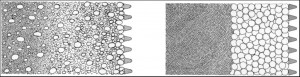
Gravel packing makes the zone immediately surrounding the well screen more permeable by removing the formation materials and replacing them with artificially graded coarser materials (Figure 1). The size of this artificially graded gravel should be chosen so that it retains essentially all of the formation particles. The well screen slot opening size is then selected to retain the gravel pack.
Gravel pack design includes specification of gradation, thickness, and quality of the gravel pack material. Part of the aquifer thickness to be screened should be evaluated by examining the samples collected during the test hole drilling. Plain casing should be set in intervals with unfavorable strata (e.g., finest sands) of the aquifer. It may be necessary to place plain (unslotted) casing between screen sections that are positioned in the best strata of the aquifer. One advantage of placing plain casing against strata composed of the finest sands and low permeability intervals is that a coarser gravel pack can be utilized. The coarser pack will allow the coarser strata of the water-bearing formation to yield maximum water. Little potential yield will be lost by setting plain casing opposite the finest sands and other low permeability strata because these layers produce little water.
A sieve analysis should be prepared for the strata comprising the portion of the aquifer where the screen will be set. Results of sieve analysis for the finest stratum should be used to design the gravel pack grading. It is best to design as uniform a pack as possible. A uniform gravel pack has significantly greater permeability and is easier to install without segregation. The gravel pack material should consist of clean and well-rounded grains that are smooth. These characteristics increase the permeability and porosity of the gravel pack. In addition, the particles should consist of siliceous (quartz) rather than calcareous material. The calcareous material should be limited to less than 5 percent.
To ensure that an envelope of gravel will surround the entire screen, a thickness of 3 to 8 inches is recommended. This thickness will successfully retain formation particles regardless of how high the water velocity tends to carry the particles through the gravel pack. When more than 8 inches of gravel pack is provided, development of the aquifer is hampered. A thicker envelope does not significantly increase the yield of the well and does little to control sand pumping because the controlling factor is the ratio of the grain size of the pack material to the formation material. To ensure that the envelope of gravel completely surrounds the entire screen, centering guides should be used to center the screen in the borehole.
The pack material should be placed continuously, but slowly, to avoid bridging and sorting of the particles. If the screen is not centered in the bore hole and is in direct contact with the formation material (no gravel pack between the well screen and formation), sand pumping will result.
Slot Openings
The gravel pack retains the water-bearing formation, while the well screen retains the gravel pack particles. In a gravel-packed well, the size of the screen slot is selected to retain 90% or more of the gravel pack material. For the sand sieve analysis in Figure 3, the proper size screen in a gravel-packed well would have a slot opening of 0.015 inch to retain 90% of the material in the water-bearing strata.
For naturally developed wells, the size(s) of well screen slot openings will depend on the gradation of the sand, and slot openings are selected using the results of sieve analyses of water-bearing formation samples. A sieve analysis curve, such as shown in Figure 4, is plotted for each sand sample. The size of the screen opening is selected so that the screen will retain 40-50% of the sand. The remaining 50-60% of the sand particles will pass through the openings during development. If the formation is heterogeneous, it may be necessary to select various sizes of slot openings for different sections of the well screen. The use of a multiple-slot screen to custom fit the gradation of each stratum will assist in attaining the highest specific capacity possible, and will greatly reduce the possibility of pumping sand with the water.
The screen opening size that retains 40% of the particles is usually chosen when the groundwater is not particularly corrosive and when there is little doubt as to the quality of the formation samples. For example, a slot size of 0.050 inch would provide 40% retention of the materials in the water-bearing strata (Figure 4). The screen opening size that retains 50% of the sand is chosen if the water is corrosive or if the reliability of the sample is in question. If the water is corrosive, enlargement of the openings of only a few thousandths of an inch due to corrosion could cause the well to pump sand. If the water is encrusting, a size that retains 30% of particles may be selected. When this larger slot opening is selected, longer well life can be expected before plugging reduces the well yield. Large slot size also makes it possible to develop a larger area of the formation surrounding the screen. This generally increases the specific capacity of the well by increasing the well efficiency.
Screen Diameter
One important consideration that must be kept in mind when selecting the screen diameter is that the diameter can be varied without greatly affecting the well yield. Doubling the diameter of the well screen can be expected to increase the well yield by only about 10%. Screen diameter can be varied after the length of the screen and size of the screen openings have been selected. Screen diameter is selected to provide enough total area of screen openings so that the average entrance velocity of the water through the slot openings does not exceed the design standard of 0.1 feet per second (3 cm/sec). A quality well screen with maximum open area offers a decided cost advantage when different types of screening devices are compared at this entrance velocity.
The entrance velocity (V) is calculated by dividing the expected or desired yield (Y) of the well by the total area (A) of openings in the screen (V = Y/A). If the velocity is greater than 0.1 foot per second, the diameter should be increased. If the calculated entrance velocity is less than 0.1 foot per second, the screen diameter may be reduced. However, the screen diameter should not be reduced to the point that the velocity of vertical water flow to the pump exceeds 5.0 feet per second. Laboratory tests and field experience show that if the screen entrance velocity is equal to or less than 0.1 foot per second, the friction loss through the screen openings is negligible, resulting in a higher well efficiency.
Open Area
The percentage of open area of the screen should be equal to or greater than the porosity of the sand and gravel in the water-bearing formation and artificial gravel pack supported by the screen. Where the irrigation well screening device provides only 2% to 5% open area, as in perforated pipe, flow restrictions are unavoidable. This is one of the most common reasons for low efficiencies of irrigation wells. Suppose that the water-bearing sand has 30% porosity (voids) and the screening device installed has only 5% open area. With such a small open area, there will be constriction of flow. As a result, there will be additional drawdown caused by increased head loss as water moves toward and into the well.
Adequate open area should be provided by the well screen to allow the desired or design yield to enter the well at velocity of 0.1 foot per second. This hydraulic characteristic of the screen is known as transmitting capacity. If the amount of open area of a screen is known, and the recommended entrance velocity of 0.1 foot per second is used, the transmitting capacity of that screen can be readily calculated. For example, a 16-inch diameter well screen of continuous slot construction with 175 square inches (1.22 square feet) of open area per linear foot of screen can transmit 55 gpm per foot of screen body at an entrance velocity of 0.1 foot per second (Y = V × A = 0.1ft/sec × 1.22 ft2 = 0.122 ft3/sec = 54.8 gpm. This amount is generally halved to allow for blockage of the screen openings by the gravel pack to arrive at a well yield per foot of screen. Note that the transmitting capacity of a screen is a hydraulic characteristic of that screen and not a measure of the yielding capability of the water-bearing formation in which the screen is installed.
Screen Material
Depending on the results of preliminary investigation, the well screen should be fabricated of materials that are as corrosion resistant as necessary. If the screen corrodes, sand and/or gravel will enter the well, which may eventually require either replacement of screen or drilling a new well.
Corrosion of screens can occur from bimetallic corrosion if two different metals have been used in the fabrication; therefore, bimetallic screen should always be avoided. Water with high total dissolved solids accelerates this type of corrosion because the water is a more effective electrolyte. Corrosion can also occur from dissolved gases in the water such as oxygen, carbon dioxide, and hydrogen sulfide.
Well plugging by the deposits of incrustation is a common problem. Such deposits plug the screen openings and the formation and/or gravel pack immediately surrounding the well screen. When incrustation is a problem, acid treatments can be used. Therefore, corrosion-resistant material should always be used to resist the attack of strong acids introduced into the well screen during treatment.
Corrosion and incrustation can occur simultaneously in some groundwater environments. The products of corrosion can relocate themselves on the screen and form incrustations that plug the screen openings much like waters which are naturally incrusting. Removal of these deposits often requires strong acids.
The choice of the well screen material is sometimes based on strength requirements regarding column load and collapse pressure. When a long screen supports a considerable weight of pipe, it functions as a slender column. The pressure of the formation and materials caving into the well pipe can squeeze the screen. Therefore, the well material should be able to withstand the pressure. It is impossible to accurately determine or calculate earth pressures with depth but generally greater strength is needed at greater depths.
Well screens can be constructed of materials which are especially adapted to resist the corrosive attack of aggressive waters and acids. Stainless steel offers the maximum in corrosion resistance for most fresh groundwater environments and it also provides good strength. Galvanized steel is suitable for many irrigation wells where the water environment is not corrosive. It provides strength comparable to stainless steel. PVC well screens are resistant to corrosion and are often used in shallow wells. However, only limited open area can be provided and still maintain strength requirements. Therefore, non-metallic well screens are not usually adequate for deep irrigation wells.
Too Much Detail?
That’s probably enough for this week. Remember, you don’t have to know anything about the detailed installation of a water borehole, since we have it all covered, but it does make interesting reading to some.
Waterseekers Well Drilling Services Ltd has over 50 years experience of commercial water well installations for agricultural and industrial usage. You dont have to know about the above definitions because we undertake the Borehole Prognosis for you.
Commercial Water Borehole Turn Key Solutions
We offer a turn-key solution that covers not just the technical aspects such as borehole prognosis, but also every requirement typical of any large commercial water borehole project:
- Insurance
- Health and Safety
- Project Management
If you would like to talk to us about your project, we are happy to give no obligation advice. Visit our website, use the contact form, or call us on 01246 938499
In Part IV, we will look at Water Borehole development, testing and potential problems.
Thanks for reading!
Jenny Hormell
Director
Waterseekers Well Drilling Services Ltd.
Post on 06 Jan 2015 by Water Well Drilling Enthusiast